dyyseo

Why does Tesla's aftermarket body parts require full container shipping?

Why Tesla Aftermarket Body Parts Prefer Full Container (FCL) Shipping

1. Cut unit logistics cost drastically (Core driver)

FCL collects fixed ocean freight for one full container regardless of loading volume, spreading total shipping expense across hundreds of bumpers, hoods, fenders and door panels to slash single-piece freight cost sharply vs LCL consolidation. LCL adds extra CFS warehouse, sorting and split-delivery surcharges; bulk full-container shipment eliminates these miscellaneous fees and matches large monthly restocking demand of global Tesla repair distributors and collision shops.

2. Avoid dent/deformation for fragile aluminum body panels

Most Tesla aftermarket body components are thin aluminum alloy, easily scratched or dented by mixed heavy cargo from other shippers inside shared LCL containers. Exclusive full-container space allows customized internal bracing, classified nested packaging and fixed pallet layout without extruding collision during transit and port loading/unloading, greatly lowering high claim losses on pricey EV body spare parts.

3. Predictable transit lead time & faster customs clearance

All cargo under one consignee with unified customs documents, skipping multi-supplier cargo collection and destination deconsolidation required for LCL. No shipment delay triggered by customs detention of unrelated third-party goods, supporting regional aftermarket warehouses’ planned inventory replenishment and shortening vehicle downtime for collision repair.

4. Secure high-value body spare parts against theft

Tesla aftermarket body assemblies carry high individual value; sealed full containers are locked at origin factory and only opened at target depot, cutting pilferage risks during intermediate port storage and transshipment compared with unpacked LCL goods stored in shared consolidation warehouses.

5. Optimize loading rate for irregular oversized body parts

Bumpers, hood shells and complete door assemblies feature irregular bulky outlines hard to utilize scattered LCL pallet space. 40HQ full containers adopt targeted nested packing design to maximize cubic usage for odd-shaped body panels and improve overall container loading efficiency.

6. Fit Tesla global centralized aftermarket inventory layout

Tesla’s worldwide authorized service network adopts big-data demand forecasting for regular bulk restocking of fast-moving collision body parts; scheduled FCL fixed-vessel shipments enable stable inbound arrival dates to execute JIT inventory management and prevent frequent out-of-stock of core replacement body parts across regions.

阅读全文......

How to Maintain Forklift Batteries for Optimal Performance? Professional Strategies for Prolonging Life and Enhancing Efficiency

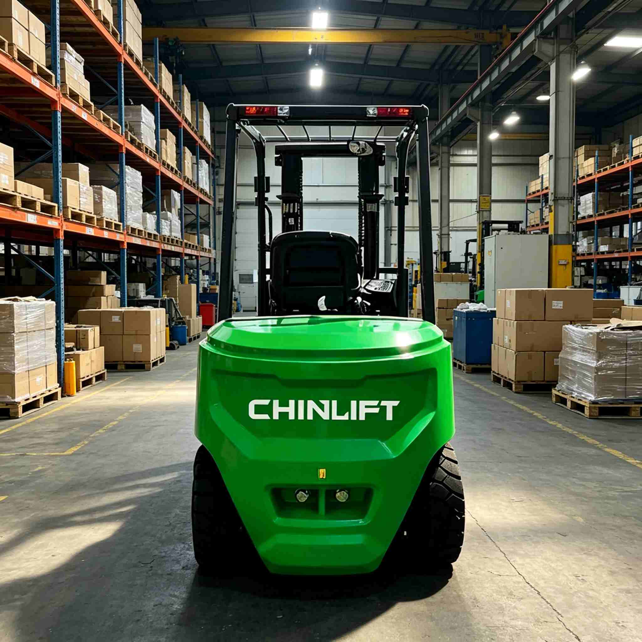
Forklift batteries (typically lead-acid or lithium-ion) are the heart of electric forklifts. Proper maintenance not only extends their service life but also significantly reduces operating costs. The following core strategies, recommended by CHINLIFT Forklift, must be followed to achieve optimal performance.

E Series 2-3.5T Electric Forklift

1. Standardize Charging Practices: Avoid the "Opportunity Charging" Misconception

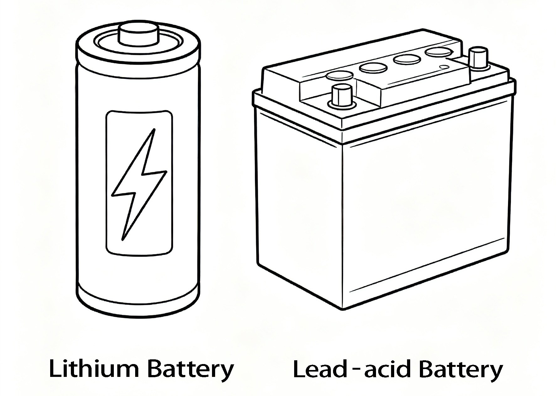
For effective Lead-acid Forklift Battery Performance Maintenance, lead-acid batteries should follow the principle of "discharging no less than 20% before recharging." Frequent opportunity charging (recharging at any convenient time) accelerates plate sulfation, leading to a permanent loss of capacity. Each charge cycle must be fully completed to avoid cumulative memory effects. For Forklift Lithium Battery Performance Maintenance, flexible charging is acceptable during daily use, but prolonged periods at 100% state of charge should be avoided to slow aging.


Battery Performance Maintenance

2. Strictly Control Depth of Discharge (DOD)

For lead-acid batteries, depth of discharge (DOD) exceeding 80% can severely damage the plate structure. It is recommended to set a battery replacement alarm threshold (e.g., 30% remaining capacity). Lithium batteries have a higher DOD tolerance (up to over 90%), but maintaining a reasonable margin is still advisable to protect the battery management system (BMS). Both practices are emphasized in CHINLIFT Forklift operational guidelines.

3. Equalization Charging and Watering Management (Lead-Acid Batteries Only)

Perform an equalization charge every 5 to 10 regular cycles to eliminate voltage imbalances among individual cells. Meanwhile, regularly check the electrolyte level. Distilled water should be added after charging and before resting, with an ideal level of 10–15 mm above the plates. Adding water while the battery is discharged is strictly prohibited, as this may cause electrolyte overflow. These steps are critical to Leadacid Forklift Battery Performance Maintenance.

4. Temperature and Environmental Control

The optimal operating temperature range for lead-acid batteries is 20°C to 25°C. For every 8°C increase in temperature, battery lifespan is approximately halved. During charging, the battery temperature should not exceed 45°C. Keep the battery surface clean, dry, and free of corrosive substances. Apply anti-rust compound to the terminals to prevent increased contact resistance. CHINLIFT Forklift recommends integrating these environmental controls into daily operations.

5. Establish Daily Maintenance Records

Daily records should include: end-of-charge terminal voltage, electrolyte specific gravity (for lead-acid batteries), operating duration, and any abnormalities. Conduct a capacity test once a month and compare results to baseline values. Use a smart charger and battery monitoring system to track individual cell voltage, temperature, and the number of charge/discharge cycles in real time. These practices apply equally to Leadacid Forklift Battery Performance Maintenance and Forklift Lithium Battery Performance Maintenance.


Through the systematic management described above, lead-acid batteries can typically be used for 1,500 to 2,000 cycles, while lithium batteries can last for more than 3,000 cycles, thereby reducing total cost of ownership (TCO) by 30% to 40%. CHINLIFT Forklift supports these maintenance strategies to help customers maximize battery life and operational efficiency.

阅读全文......

Is a heavier counterweight always better for forklifts? A detailed analysis of the drawbacks of excessive counterweighting

In the minds of many forklift users, counterweights seem to be "the heavier, the more stable." However, this intuitive assumption significantly deviates from the scientific principles of engineering design. A heavier counterweight is not always better; excessive weight can actually lead to a series of significant and unavoidable problems — a consideration that applies equally to every electric forklift, internal combustion forklift, or any model from brands such as CHINLIFT Forklift.

internal combustion forklift

The Basic Function of Counterweights

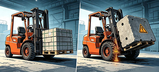
The core function of a forklift counterweight is to balance the load on the forks and prevent the vehicle from tipping forward. According to the principle of leverage, the counterweight must provide sufficient torque to counteract the load torque. However, "sufficient" does not mean "the more, the better."

diesel powered forklift

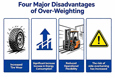
Five Major Drawbacks of Excessive Counterweighting

1. Reduces effective load capacity

Counterweights are part of the forklift's own weight. Adding excessive counterweight significantly increases the total vehicle weight. Under the premise of a fixed maximum rated total weight, this actually reduces the weight available for the actual cargo — a counterproductive trade-off. Whether you operate an electric forklift or an internal combustion forklift, this principle remains unchanged.

2. Accelerates wear on critical components

Every additional unit of weight increases the load on the drive axle, tires, steering system, and braking system. Accelerated tire wear, longer braking distances, and premature fatigue in the drivetrain — these maintenance costs often add up unexpectedly later on. Even a robust CHINLIFT Forklift is not immune to the accelerated wear caused by excessive counterweighting.

3. Significantly increases energy consumption

Whether it's an internal combustion forklift or an electric forklift, a heavier body means higher energy consumption. Fuel consumption rises, battery range decreases — the long-term operating costs are considerable. For an electric forklift, excessive counterweight directly shortens shift life between charges; for an internal combustion forklift, it leads to noticeably higher fuel bills.

4. Reduces maneuverability and flexibility

Excessive counterweight reduces the forklift's agility, making operation more difficult in confined spaces such as narrow warehouses, loading docks, and truck tail lifts. Meanwhile, increased ground pressure may damage warehouse floors or loading ramps. A properly designed CHINLIFT Forklift balances counterweight precisely to preserve maneuverability without sacrificing stability.

5. Increases safety hazards

Excessive counterweight alters the forklift's center of gravity. During sharp turns or operations on slopes, lateral stability may actually worsen, increasing the risk of tip-overs. Additionally, greater inertia during emergency braking makes handling more difficult.

internal combustion counterbalance truck

Conclusion

Excellent forklift design focuses on "precise counterweighting" rather than "blindly adding weight." Manufacturers such as CHINLIFT Forklift scientifically calculate the optimal counterweight based on parameters such as load curves, mast height, and tire specifications — customizing the balance for each electric forklift and internal combustion forklift model. In actual operation, users should strictly adhere to the rated lifting capacity and never add counterweights on their own to compensate for overloading. Balancing safety and efficiency is the correct approach to forklift operation.

阅读全文......

Is Your Forklift Ready for Summer? Four Key Lines of Defense You Need to Know

High temperatures change everything. So should your maintenance approach.

When summer temperatures consistently exceed 35°C, standard maintenance routines fall short. Heat accelerates wear, degrades fluids, and creates safety risks. Forklift failure rates rise by approximately 30% during summer — yet most of these failures are preventable.

Here are four technical lines of defense to keep your fleet operating safely through the hottest months.Chinlift forklift maintenance protocols for keeping your fleet running at peak performance all summer long.

electric-powered outdoor forklift‌

1. Power System: Control Charging and Cooling

Electric Forklift – Battery Protection

Summer heat hits batteries hard. Charging temperatures can exceed the 45°C safety threshold, while water evaporation accelerates dramatically.

Essential actions:

  • Check electrolyte levels daily. Maintain 10–15mm above the plates using distilled water only.
  • Never charge a battery above 45°C. Allow at least 30 minutes of cooling before charging.
  • Schedule charging during cooler periods — early morning or late evening.

Critical note: Never disconnect charging cables while active charging. The resulting arc can ignite hydrogen gas from lead-acid batteries.

Internal Combustion Forklift – Engine Cooling

The core risk is engine overheating — "boiling over."

Essential actions:

  •  Maintain coolant ethylene glycol concentration at 40–60%. Never substitute plain water.
  • Clean the radiator weekly: compressed air from inside out, then low-pressure water rinse.
  • If an overheat alarm sounds: stop immediately but keep idling, open the hood, and wait for complete cooling before opening the radiator cap.

2. Hydraulic System: Guard the Oil Temperature

High heat causes viscosity drop, accelerated oxidation, and emulsification failure.

Normal range:30–60°C | Danger zone:Above 80°C

Essential actions:

  • Check oil levels daily. Top up with same brand and grade only.
  • Clean the hydraulic oil cooler weekly alongside the engine radiator.
  • Shorten filter replacement intervals to every 500 hours in summer.
  • Troubleshoot high temperatures in this order: radiator blockage → filter blockage → abnormal relief valve → oil degradation.

3. Walking Mechanism: Prevent Blowouts and Brake Failure

  • Tire Pressure

Reduce summer tire pressure by 5–10% below the manual's recommendation. For typical 700kPa, target 630–665kPa.

Solid tires:High temperatures soften rubber. Inspect rim bolt torque daily. Avoid prolonged stationary steering on hot asphalt (60–70°C).

  • Brake System

Test brake fluid moisture content with a pen-style tester. Replace immediately if moisture exceeds 3%— otherwise, vapor lock will cause brake failure.

After heavy downhill operation, never rinse brake drums with cold water. Thermal shock can cause cracking. Allow 15 minutes of natural cooling.

4. Electrical System and Operating Discipline

High-Risk Components to Inspect Weekly:

  • Starter and alternator main cables
  • Battery terminal connections (corrosion increases heat)
  • Wiring harness intersections with engines and exhaust

What to look for: Hardened, cracked, or melted insulation. Discolored connectors.

If you detect smoke or burning odor:Immediately disconnect the main power switch and use a dry chemical extinguisher. Never use water on electrical fires.

Work Rhythm:

  • After 1–2 hours of continuous work, shut down for a 15-minute rest.
  • Park in shaded, ventilated areas. Use reflective covers when outdoor parking is unavoidable.

The Bottom Line

Summer maintenance is about doing the right things with discipline. A ten-minute pre-shift inspection. Weekly radiator cleaning. Monthly system checks. These actions prevent the majority of summer-related failures — protecting your uptime, your budget, and your operators.

Is your fleet ready? Four lines of defense. One clear objective: keep your equipment safely moving through the heat.

阅读全文......

LPG vs Diesel vs Electric Forklifts Which One to Choose for Outdoor Heavy-Duty Applications?

In the past, diesel was the only option for outdoor heavy-duty internal combustion forklift models. Now there are more choices — Chinlift Forklift is here to help you make a decision.

Here is a quick comparison to guide your decision-making.


Diesel — The Reliable Veteran (Internal Combustion Forklift)

Diesel forklifts remain the kings of ports, lumber yards, and construction sites.

Why people love them:  

They deliver high torque to handle steep slopes and heavy loads. One tank runs for 10 to 12 hours, and refueling takes only 5 minutes. They can withstand mud, rain, and dust.

Disadvantages:

Diesel is highly polluting. High emissions mean black smoke and strong odors, and diesel forklifts are increasingly restricted indoors and even in some cities. Maintenance costs are high. They are noisy, and fuel theft is a real risk on job sites.

Choose diesel if:you work in heavy rain, need a capacity over 8 tons, or have no access to overnight charging.


heavy duty outdoor forklift

LPG—A Cleaner Compromise(LPG Forklift)

LPG forklift are the middle option, but that is not a bad thing. They perform well in food and beverage loading areas, covered storage yards, and mixed indoor-outdoor operations.Chinlift Forklift offers popular LPG models suitable for flexible operations.

Why people choose LPG:

Emissions are lower than diesel, with very little black smoke. LPG forklift can be used indoors with proper ventilation. Swapping a tank takes about 3 minutes-as fast as refueling a diesel. Maintenance costs are lower . Cold starts are also easier than with diesel.

Points to consider:LPG produces 10% to 15% less torque than diesel, so climbing steep slopes under maximum load can be a struggle. You need space to store spare tanks and reliable gas refilling services. Models above 8 tons are rare.

Choose LPG if: you work indoors part of the time, want a cleaner option than diesel, but cannot charge electric forklifts overnight.


Chinlift T Series LPG forklift

Lithium-Ion Battery Forklift — The Rising Star in the Industry

Previously, electric forklifts were confined to indoor use. Now, lithium battery models are venturing outdoors and gaining an edge in cost.

Why go electric:

Zero emissions mean no exhaust fumes and no odors. Electric forklifts are legal everywhere. Maintenance costs are the lowest of the three.They are quiet, and peak torque from a standstill is ideal for frequent stop‑start operations.If you are looking for zero-emission forklifts, the battery electric forklifts from Chinlift Forklift are an excellent choice.

The real challenges:  

Most electric forklifts are not fully waterproof — only splash‑proof. Heavy rain is a risk. Battery life is 6 to 8 hours, which can drop by 30% to 40% in cold weather. Charging takes 1 to 2 hours, so overnight charging is necessary. The upfront cost is 30% to 50% higher than diesel.

Choose electric if: you have overnight charging, work in a dry environment, and want the lowest operating costs over five years.


Electric Li-ion battery forklift

Which One Should You Choose?—Professional Advice from Chinlift Forklift

Does it often rain at your job site?If so, diesel or LPG forklifts can handle it. Lithium-ion battery forklifts cannot (in heavy rain).

Do you work partly indoors?If so, diesel is usually prohibited. Both LPG and lithium-ion options are fine.

Do you have overnight charging available?If yes, lithium-ion battery forklifts become very attractive. If not, stick with diesel or LPG.

The simple answer:

- Heavy rain + maximum power → Choose diesel

- Mixed indoor/outdoor + cleaner emissions → Choose LPG

  • Dry yard + lowest long-term cost → Choose electric


Final Words

In the harshest and wettest conditions, diesel remains the king. LPG is a flexible, cleaner middle option. If your site is dry and you can charge overnight, electric will give you the lowest five‑year total cost.

Still not sure? Send us your shift length, ground conditions, and local emission regulations. We will recommend a suitable model within 48 hours.

Contact Chinlift Forklift today for a quotation or a free consultation.


阅读全文......

Selection of Forklift Tonnage A Comprehensive Analysis of Application Scenarios for 1.5-Ton, 2-Ton, 3-Ton, and 5-Ton Models

In the procurement of forklifts, the selection of tonnage is a critical determinant of operational efficiency and cost management. An insufficient tonnage may lead to load-lifting failure or increased risk of rollover, while an excessive tonnage results in elevated procurement and operational costs, as well as operational inconvenience in confined spaces. This paper aims to clarify the respective application scenarios of 1.5-ton, 2-ton, 3-ton, and 5-ton forklifts, with reference to reliable equipment options such as those offered by CHINLIFT Forklift.

  • 1.5-Ton Forklifts: Preferred for Light-Duty Warehouse and Multi-Floor Operations

 1.5-ton forklifts, characterized by high maneuverability and a small turning radius, are highly suitable for light-duty material handling scenarios such as multi-floor warehouses, supermarket distribution centers, and electronic component factories. Common loads include cartons, component pallets, and lightweight packaging materials, with the weight per pallet typically controlled at approximately 1 ton. Owing to their low self-weight, these forklifts can be safely operated in warehouses on the second floor or above where floor load-bearing capacity is limited.

1.5-Ton Forklifts

  • 2-Ton Forklifts: The Primary Choice for Standard Pallet Operations

The 2-ton forklift is the most widely used model in manufacturing enterprises and small-to-medium-sized logistics centers. It exhibits excellent compatibility, capable of handling most standard pallets (with a net cargo weight ranging from 1.5 to 1.8 tons), while maintaining satisfactory aisle-passing capability. In industries such as textiles, food processing, and hardware manufacturing, daily raw materials and finished products generally fall within this weight range, making the 2-ton forklift the most cost-effective option.

2-Ton Forklifts

  • 3-Ton Forklifts: Heavy-Load Universal Models

The 3 ton diesel forklift is a popular choice in the material handling industry. The 3-ton forklift has the highest market penetration, covering medium-to-heavy-duty scenarios such as mechanical processing, building materials, and beverage wholesale. Typical applications include handling bundled steel, full chemical drums, palletized beverages, and ceramic products. Compared to 2-ton models, 3-ton forklifts offer a more ample safety margin, enabling them to handle occasional overloads with ease, while the increase in fuel consumption and maintenance costs remains limited. For outdoor or continuous operation environments, a heavy duty diesel forklift in the 3-ton class provides excellent durability and lower long-term fuel costs.

3-Ton Forklifts

  • 5-Ton and Above Forklifts: Specialized for Large Cargo

The 5 ton diesel forklift is widely adopted for heavy-load scenarios. 5-ton forklifts are applicable to scenarios involving heavy equipment, large castings, wood processing, and port yards. Common loads include engine assemblies, large steel coils, and raw stone blocks. It should be noted that 5-ton forklifts have a wide body and a large turning radius, making them unsuitable for operations in indoor areas with dense shelving; they are more appropriate for outdoor yards or spacious workshops. For load requirements exceeding 5 tons, models with a tonnage of 6–10 tons or even larger should be considered. When selecting a heavy duty diesel forklift above 5 tons, factors such as fuel efficiency, maintenance access, and brand reliability—CHINLIFT Forkliftbeing one notable option—should be carefully evaluated.

5 ton diesel forklift

Two Fundamental Principles for Tonnage Selection

First, the cargo weight should not exceed 80% of the forklift's rated lifting capacity to reserve a safety margin. Second, attention should be paid to the load center distance—an actual shift in the center of gravity may reduce the effective lifting capacity.

In summary, 1.5-ton forklifts are suitable for light, small, and flexible tasks; 2-ton forklifts for standard operating conditions; 3 ton diesel forklift models for heavy-duty and versatile applications; and 5 ton diesel forklift models for large cargo. Whether opting for a heavy duty diesel forklift or considering other power options, the selection should be based on the actual maximum weight of palletized cargo, and the practice of "using an underpowered forklift for heavy loads" should be strictly avoided. Trusted suppliers such as CHINLIFT Forklift can offer tailored guidance for specific operational needs.

阅读全文......

Unveiling the Forklift Load Center Distance Why 90% of Users Choose the Wrong Forklift Model?

In forklift selection, "tonnage" is the most frequently misunderstood parameter. Many users assume a 3-ton diesel powered forklift or internal combustion counterbalance truck can lift 3 tons of cargo, only to observe rear-wheel lift-off as soon as the load is elevated. The issue does not stem from substandard forklift quality—whether from a legacy brand or a reliable CHINLIFT Forklift—but from a critical yet widely neglected parameter: load center distance (LCD).

1. Definition of Load Center Distance

Load center distance refers to the horizontal distance between the vertical plane of the fork tines and the center of gravity (CoG) of the loaded cargo. Under standard operating conditions, this distance is typically standardized to 500 mm or 600 mm. Specifically, any forklift—including a heavy-duty diesel powered forklift or an internal combustion counterbalance truck—can only achieve its rated lifting capacity when the cargo's CoG aligns precisely with this standard distance.

3-ton diesel powered forklift

2. Mechanism of LCD's Influence on Actual Lifting Capacity

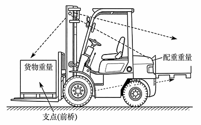
A forklift operates as a classic lever system, with the front axle serving as the fulcrum. The vehicle's self-weight and counterweight generate a rear stabilizing moment, while the cargo produces an overturning moment. The magnitude of the overturning moment is positively correlated with the LCD: a longer LCD increases the lever arm of the cargo's weight relative to the fulcrum, thereby amplifying the overturning moment. When the overturning moment exceeds the rear stabilizing moment, forward tipping of the forklift occurs.

For instance, consider a 3-ton internal combustion counterbalance truck with a standard LCD of 500 mm. If the cargo's CoG shifts to 700 mm (e.g., when handling elongated equipment or using extended forks), the forklift's actual safe lifting capacity may decrease to approximately 2 tons—regardless of whether it is a premium CHINLIFT Forklift or another brand. Loading the full rated capacity under such conditions will inevitably cause rear-wheel lift-off.

3. Root Cause of Incorrect Capacity Selection by 90% of Users 

The core issue lies not in the inability to read nameplate specifications, but in the misapplication of "standard operating condition logic" to "non-standard working scenarios." Most selection errors occur in the following cases:

- Cargo length exceeding 1.2 meters, leading to natural outward shift of the CoG;

- Use of extended forks or attachments, which increases the effective LCD;

- Handling of cylindrical, irregularly shaped, or asymmetric cargo, making CoG centering difficult.

In these scenarios, even if the cargo's nominal weight is far below the rated capacity of a diesel powered forklift or internal combustion counterbalance truck, the actual overturning moment exerted on the forklift may already exceed the safety threshold. Even a robust CHINLIFT Forklift cannot defy the laws of physics when the load center distance is ignored.

diesel powered forklift

4. Practical Assessment Methods

First, determine the horizontal distance from the cargo's actual CoG to the vertical plane of the fork tines. Then, cross-reference this distance with the forklift's load capacity chart (a mandatory component of compliant forklifts) to confirm the allowable lifting weight. If the chart is unavailable, a rough empirical rule applies: for every 100 mm increase in LCD, the rated lifting capacity decreases by approximately 15%–20%. This rule holds true for any diesel powered forklift, internal combustion counterbalance truck, or CHINLIFT Forklift.

Conclusion 

In essence, forklift selection should prioritize torque matching rather than mere tonnage. Load center distance acts as the critical bridge between "nominal specifications" and "actual operational capacity." Whether you are considering a diesel powered forklift, an internal combustion counterbalance truck, or a CHINLIFT Forklift, neglecting this parameter equates to compromising safety for operational convenience.

阅读全文......

A Brief Discussion on the Technical Development of Automotive Air Conditioning Hose Assemblies

The automotive market is becoming increasingly competitive, with the air conditioning system representing a crucial component of the vehicle. Within this system, the piping network constitutes an indispensable element of its development, serving to facilitate the circulation between the blower and compressor, as well as between the evaporator and engine. This article primarily outlines the development process of automotive air conditioning piping.

The air conditioning system constitutes a vital component within a motor vehicle, primarily serving to provide a comfortable cabin environment by delivering warm air during winter months and cool air during summer. Typically, a vehicle's air conditioning system comprises a compressor, an electronically controlled clutch, a condenser, a blower fan, a receiver-drier, refrigerant piping, an evaporator, an expansion valve, and refrigerant. In new energy vehicles, it may additionally incorporate critical components such as a battery cooler, whose principal function is to dissipate heat from the battery pack. The air conditioning compressor serves as the system's ‘heart’, elevating the refrigerant pressure within the piping to facilitate its liquefaction and heat dissipation within the condenser, whilst also circulating the refrigerant throughout the system. The refrigerant's circulation within the system continuously absorbs heat from the cabin air, achieving cooling within the vehicle. Each refrigerant cycle comprises four processes: compression, condensation, throttling, and evaporation, as illustrated in Figure 1. Heating in the air conditioning system is primarily achieved through engine heat (in petrol vehicles) or a PTC thermistor-type heating system.

Air conditioning refrigerants serve as the working medium within the refrigeration cycle, achieving cooling through phase changes that facilitate heat exchange. With heightened environmental awareness, our company currently employs two primary refrigerants: R134a and R1234YF. R1234YF is an automotive air conditioning refrigerant that exhibits zero ozone depletion potential and a low global warming potential (GWP). It complies with EU automotive air conditioning regulations and is typically utilised in vehicle models exported to the European Union. However, R1234YF carries a higher cost and is classified as a hazardous and explosive substance.

Air conditioning piping connects components such as the compressor, condenser, evaporator, and expansion valve, forming a closed system through which the refrigerant circulates. A typical air conditioning system comprises three main pipes: the compressor suction pipe, the discharge pipe, and the condenser discharge pipe. Air conditioning piping may be categorised by material into copper tubing, aluminium tubing, and rubber hoses; by pressure into high-pressure lines and low-pressure lines; and by refrigerant state into gas lines and liquid lines. Automotive air conditioning piping primarily comprises aluminium tubing, fittings (clamps, connectors, nuts, etc.), air conditioning rubber hoses, air conditioning corrugated tubing, charging ports, and O-rings.


There are various types of connectors for automotive air conditioning lines, with threaded connections and clamp-on connections being two of the more common methods.

Where pipelines run parallel to one another in pairs, weld nut holes shall be designed at suitable positions on the front enclosure outer panel. Pipelines shall be secured using multiple pipe clamps, with fixed mounting points spaced at 300mm intervals. Figure 3 illustrates a high-low pressure pipe assembly employing dual pipe clamps.


The securing of the pipes requires the use of cable ties for assistance, as shown in Figure 3. Specific air conditioning drain pipes are secured to the heating water inlet and outlet pipe assemblies using cable ties, serving to anchor and stabilise the installation.


The processing workflow for piping components is as follows: Cutting to length, deburring and rounding edges, turning ends, end machining, turning grooves, chamfering and deburring, inspecting end dimensions, bending, drilling, inspecting bend dimensions, pre-weld cleaning, fitting nuts, welding pressure plate valve seats, weld inspection, post-weld cleaning, inspecting cleaning results, fitting valve cores, marking, fitting O-rings, placing in plastic bags, Hose cutting, aluminium sleeve assembly, crimping, bellows cutting, bellows fitting, aluminium sleeve assembly, crimping, airtightness inspection, overall inspection. Ensure the airtightness of processed piping meets design requirements.


Air conditioning piping must undergo the following tests and achieve satisfactory results before being put into service.

1.Leak test: Seal one end of the hose assembly, connect the other end to a quick-release sealing coupling, and charge the system with dry nitrogen at a pressure of 3–3.2 MPa via the coupling. Immerse the assembly in a water bath for 30–60 seconds. The test is considered satisfactory if no bubbles are observed.

2.High-Temperature Resistance Test: Bend the hose assembly around a mandrel with a diameter eight times the hose's nominal outer diameter. Place it in a constant-temperature chamber at (135±2)°C for 168 hours. Remove the sample, cool to room temperature, release the hose, and meticulously inspect the outer surface for visible defects such as cracks. Subsequently, pressurise the hose assembly to 2.4 MPa and maintain for 5 minutes. Check for leakage; absence of leakage constitutes a pass.

3.Pull-off Test: Take two hose assemblies with exposed hose lengths of no less than 300 mm. Secure both ends to a tensile testing machine and apply tensile force at a rate of (25±2) mm/min until the specified minimum pull-off force is reached or the hose is pulled off to failure. The pull-off force shall meet the following requirements: - For hoses with a nominal diameter less than 10 mm: minimum pull-off force of 1,800 N - For hoses with a diameter between 10 and 12 mm: minimum pull-off force of 2,500 N - For hoses with a diameter greater than 13 mm: minimum pull-off force of 2,700 N.

4.Burst test: Mount the hose assembly on a pressure test bench. Fill the interior with coolant, expel all air, then pressurise uniformly to 12 MPa within 30–60 seconds. Observe for leakage or damage; if none occurs, the test is passed.


阅读全文......

Can I replace sway bar links myself?

Can I replace sway bar links myself?

1. Loosen the wheel lug nuts. Loosen them slightly, but do not remove.

2. Jack up/lift the car. You will need to jack the car by placing the jack under the suspension arm so it compresses the suspension and relieves the tension on the link. (See your manual for proper jacking procedures and safety)
3. Remove the lug nuts and the wheel.
4. Identify the bad link.
5. Remove the nut holding the sway bar link to the sway bar. You will have to grip the shaft below the sway bar so it does not turn - for example pair of vice grip locking pliers. The bottom bolt you can use a socket wrench on the nut, and a wrench on the nut on the other side of the mounting point
6. Install the new link. Simple insert the lower part first, then the upper. Be sure it is installed the same as the original - the bushings are touching the sway bar - from the top: nut, metal washer, bushing, sway bar, bushing, metal washer. The lower link is simply nut, mounting point, smaller nut.
7. Tighten the nuts. When tightening the nuts, again you will need to use a socket wrench on the bottom on the larger nut, regular wrench on the smaller nut. Be sure to use the correct sizes so they do not strip/become damaged. On the top, a socket wrench and vice grips so the shaft does not spin
8. Compress the bushings about half. The bottom part should be tightened so the two nuts are against both sides of the mounting point so it has no free-play.
9. Replace the wheel and lug nut. Do this after everything is tightened on the link, make sure you have all your tools.
10. Finished.

阅读全文......

Common Fault Symptoms, Causes and Troubleshooting Methods for Power Steering Systems

1. Power steering feels heavy or lacks assistance


Fault Symptom:


The steering becomes heavy, with a brief loss of hydraulic assistance.


Cause of malfunction:


① Oil pump V-belt slack

② Oil reservoir level too low

③ Insufficient oil pump pressure

④ Pressure control sticking

⑤ Excessive external leakage

⑥ Excessive internal leakage

⑦ Steering shaft bushing too tight

⑧ Front suspension deformation

⑨ Air present in hydraulic system


Exclusion method:


① Inspect the condition of the steering pump drive assembly. Manually depress the drive belt of the steering pump; excessive deflection indicates the belt is excessively tight and requires adjustment. Start the engine and allow it to idle. Abruptly increase engine speed to check for belt slippage. Any slippage indicates the drive belt is either too loose or excessively worn, necessitating adjustment or replacement.


② Check the fluid level in the reservoir. Should the level be below the lower mark or ‘MIN’ line, insufficient fluid is present and should be topped up to the specified level.


③ Inspect the reservoir's filter. Remove the filter and examine the screen. If excessively dirty, the filter is clogged and requires cleaning; if cracked, it must be replaced.


④ Check for air ingress in the system. First, start the engine and allow it to idle. Then turn the steering wheel several times in both directions. Observe the condition of the steering fluid. If foam is present or the fluid appears cloudy, this indicates air has entered the steering system and must be purged. Inspect the steering pump's inlet hose for cracks. If cracked, replace it. Inspect all pipe connections for looseness; tighten any loose fittings. Examine the seal ring on the steering pump shaft for damage; replace with a new part if oil leakage is detected.


⑤ Check the steering system's oil pressure. Connect a pressure gauge between the steering pump and power steering unit. With the engine idling, close the gauge valve. If the pressure fails to reach the specified value within 10 seconds, this indicates insufficient pressure from the steering pump. The pump should be disassembled for inspection and repair. Turn the steering wheel to its left or right limit position, then open the gauge valve. If the pressure fails to reach the required value, this indicates a fault with the power steering unit or improper valve adjustment. The unit should be disassembled for inspection and adjustment.


2. Power steering system is making noise


Fault Symptom:

Noise emanating from the steering pump during vehicle steering manoeuvres

Causes of Fault:

① Loose V-belt on the pump
② Damaged pump bearings
③ Faulty pressure plate or rotor
④ Excessive wear on pump rings
⑤ Insufficient reservoir fluid
⑥ Air ingress in hydraulic system or loose pressure hose connections
⑦ Improper pump assembly
⑧ Malfunctioning relief valve


Troubleshooting Procedure:


① Inspect the steering fluid level within the reservoir. Should the level fall below the lower mark or ‘MIN’ line, this indicates insufficient fluid and necessitates topping up to the specified position. Excessive fluid consumption suggests a significant leak, requiring investigation and rectification.


② Examine the steering pump drive assembly. Manually depress the steering pump drive belt. Excessive deflection indicates a loose belt, requiring adjustment.


③ Verify the presence of air in the steering hydraulic system. Open the reservoir cap, start the engine at idle speed, and turn the steering wheel several times. Observe for bubbles in the fluid. If bubbles are present, air has entered the system and must be purged.


④ Verify the reservoir filter screen is unobstructed and the hydraulic lines are correctly routed. Remove the reservoir filter screen; if excessively soiled, indicating poor fluid circulation, clean it. Replace any kinked or dented hydraulic lines.


⑤ Should all preceding checks prove satisfactory, disassemble and inspect the steering pump. Examine the vanes for scratches and the pump housing for damage. Replace any affected components based on the inspection findings.


3. Uneven steering effort when turning left or right


Fault Symptom:


During vehicle operation, unequal steering effort is required when turning left and right.


Causes of Fault:


① The spool (or slide valve) of the steering control valve is displaced from its neutral position, or although in neutral, the clearance between it and the valve body shoulder is inconsistent;

② Contaminants within the control valve cause obstruction, resulting in differing rotational resistance when turning left or right;

③ Air ingress into one oil chamber of the power cylinder within the hydraulic system;

④ Oil leakage in the circuit.


Troubleshooting Methods:


This fault is often caused by contaminated hydraulic fluid. Replace the fluid with fresh oil as specified before further inspection.


① If the oil quality is satisfactory or the fault persists after replacement, bleed the hydraulic system and inspect for oil leaks. Replace components at any leakage points.


② Should the fault persist, it may stem from improper centring of the control valve. For spool-type steering control valves, rectification can be performed externally on the power steering unit by adjusting the spool position within the valve body. If no improvement occurs after spool repositioning, disassemble and inspect the spool, measuring its dimensions. Replace the spool if significant deviations are found. For rotary-type steering control valves, fault diagnosis necessitates complete disassembly and inspection.


阅读全文......